 |
| Powerpole Polarity Checker Circuit Diagram From Hands-On Radio: Experiment 120: Power Polarity Protection, January 2013 QST; copyright ARRL |
We are big fans of Anderson Powerpole connectors and recabled our radio gear with the connector sometime ago. A polarity checker would be a very useful item to have around the shack and in a go-kit.
Step 0: Round up the parts and tools
A well-stocked junk box and workshop will likely yield all the necessary parts needed to build the polarity checker. A few minutes of scrounging around our workshop is all it took to find the parts for this project.- Green LED
- Red LED
- 1k Ohm resistor 1/4W
- Pair of Anderson Powerpole connectors
- Junk box plastic part to turn into an end-cap
- Hot glue gun
- Soldering iron
- Shrink wrap tubing (small diameter)
- Wire snips
Step 1: build the circuit on a solderless breadboard
We find it helpful to first build a circuit on a solderless breadboard prior to assembly and soldering. This approach helps confirm the junk-box parts are still functional, the circuit works as advertised, as well as verifying the orientation of parts having polarity (e.g. the LED's in this project). This circuit is very simple. The key is to make sure the LED's are wired together in opposite polarity. |
| NJ2X first built the polarity checker on a solderless breadboard as a test |
Step 2: Prepare the end-cap
We found some sort of plastic cap in our junk box that would marry up perfectly to the back side of a pair of Anderson Powerpole connectors. We drilled four small holes in the top of the cap to pass the LED's leads through. |
| NJ2X drills four holes in a small cap for the LED leads |
Step 3: Solder the components together
Insert the leads of the two LED's on the top of the cap. Solder the leads and resister together per the wiring diagram. Use shrink wrap tubing to insulate the leads from each other to prevent a short. Solder a short red wire and back wire to the leads. Again use shrink wrap tubing to insulate the connections. Solder the Anderson Powerpole connectors onto the wire ends. Be sure the Powerpole positive and negative are tied together in the correct configuration, "Red Right Up". Test the circuit to confirm it is working before proceeding with final assembly. |
| NJ2X testing the soldered polarity checker prior to final assembly |
Step 4: Final Assembly
Fill the cap with a generous amount of hot glue. You want enough glue to assure a solid mechanical connection and prevent the wires from moving or being stressed during use. Press the wire and Anderson Powerpole connectors into the cap and hot glue. Let the glue cool and harden. Test again to confirm the circuit is functional with both correct and reversed polarity. We used a label maker to add our call sign to the outside.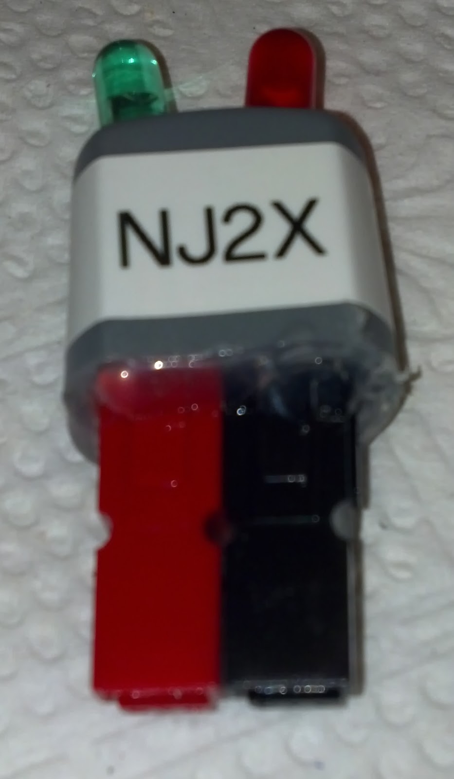 |
| NJ2X's Anderson Powerpole polarity checker fully assembled |
We shared a picture of the finished product with N0AX and he pointed out that it looked a little like a rabbit. My son, KC2VSR gave the polarity checker a funny bunny face to really set off the effect. We had a good laugh and decided to call the polarity checker, "Bunnicula". Ham radio is really a wonderful hobby to share with kids.
Voila! There is our build of a very handy 12v Anderson Powerpole polarity checker. Use the polarity checker before plugging into an unverified Anderson Powerpole connector. This simple test may save your equipment from damage. A lit green LED denotes correct polarity and lit red LED indicates reversed polarity.
There are at least a couple of potential failure modes that would cause the polarity to be reversed on a pair of Powerpole connectors. One potential failure is that the red wire terminating at the power supply was accidentally connected to the negative terminal. Another possibility is that the Powerpole connectors were snapped together with the incorrect orientation.
For example, when volunteering during an emergency and you need to recharge your HT's battery from the HQ emergency power via a Powerpole. If you plug into it without checking polarity you may end up with a dead HT if the cable was wired incorrectly to the supply.
Not all cars are wired so the center of the cigarette lighter connector is positive. If you use an Anderson Powerpole to Cigarette Lighter adapter on an unfamiliar vehicle you may be in for an unpleasant surprise when you connect your rig and the reversed polarity causes damage.
An additional use of the polarity checker is a quick power cable or connector continuity checker. We plan to put our polarity checker to good use in the shack testing all new cables and Anderson Powerpole connectors that we build for mechanical contact, continuity, and polarity. In the past, we have simply used a multimeter which didn't confirm that the connector makes proper electrical contact when connected mechanically to another Powerpole.
Good DX and 73, NJ2X
Other related articles on NJ2X.COM
© Michael W. Maher and NJ2X.COM, 2012. Unauthorized use and/or duplication of this material without express and written permission from this blog’s author and/or owner is strictly prohibited. Excerpts and links may be used, provided that full and clear credit is given to Michael W. Maher and NJ2X.COM with appropriate and specific direction to the original content.
 |
| NJ2X's Homebrew Anderson Powerpole Polarity Checker |
Voila! There is our build of a very handy 12v Anderson Powerpole polarity checker. Use the polarity checker before plugging into an unverified Anderson Powerpole connector. This simple test may save your equipment from damage. A lit green LED denotes correct polarity and lit red LED indicates reversed polarity.
There are at least a couple of potential failure modes that would cause the polarity to be reversed on a pair of Powerpole connectors. One potential failure is that the red wire terminating at the power supply was accidentally connected to the negative terminal. Another possibility is that the Powerpole connectors were snapped together with the incorrect orientation.
For example, when volunteering during an emergency and you need to recharge your HT's battery from the HQ emergency power via a Powerpole. If you plug into it without checking polarity you may end up with a dead HT if the cable was wired incorrectly to the supply.
Not all cars are wired so the center of the cigarette lighter connector is positive. If you use an Anderson Powerpole to Cigarette Lighter adapter on an unfamiliar vehicle you may be in for an unpleasant surprise when you connect your rig and the reversed polarity causes damage.
An additional use of the polarity checker is a quick power cable or connector continuity checker. We plan to put our polarity checker to good use in the shack testing all new cables and Anderson Powerpole connectors that we build for mechanical contact, continuity, and polarity. In the past, we have simply used a multimeter which didn't confirm that the connector makes proper electrical contact when connected mechanically to another Powerpole.
Good DX and 73, NJ2X
Other related articles on NJ2X.COM
- PROJECT: ANDERSON POWERPOLE POLARITY CHECKER - W3OW'S BUILD
- Project: Tiny Mint Tin Switched 9v Battery to Anderson PowerPole
- Project: PicoKeyer Plus Kit
- How To: Lock Together Anderson PowerPole Connectors
- Project: Anderson Powerpole to 2.1mm Connector Pigtail
- Project: Car power adapter to Anderson Powerpole
© Michael W. Maher and NJ2X.COM, 2012. Unauthorized use and/or duplication of this material without express and written permission from this blog’s author and/or owner is strictly prohibited. Excerpts and links may be used, provided that full and clear credit is given to Michael W. Maher and NJ2X.COM with appropriate and specific direction to the original content.