- I will listen, and listen, and then listen again before calling.
- I will only call if I can copy the DX station properly.
- I will not trust the DX cluster and will be sure of the DX station's call sign before calling.
- I will not interfere with the DX station nor anyone calling and will never tune up on the DX frequency or in the QSX slot.
- I will wait for the DX station to end a contact before I call.
- I will always send my full call sign.
- I will call and then listen for a reasonable interval. I will not call continuously.
- I will not transmit when the DX operator calls another call sign, not mine.
- I will not transmit when the DX operator queries a call sign not like mine.
- I will not transmit when the DX station requests geographic areas other than mine.
- When the DX operator calls me, I will not repeat my call sign unless I think he has copied it incorrectly.
- I will be thankful if and when I do make a contact.
- I will respect my fellow hams and conduct myself so as to earn their respect.
November 30, 2012
DX Code of Conduct
November 29, 2012
Christian Doppler - Birthday November 29, 1803
Today, we remember the mathematician and physicist Christian Doppler who was born on this day November 29, 1803. Doppler proposed that the observed frequency of a wave depends on the relative speed of the source and the observer. The Doppler effect occurring with sound waves was verified in 1845 by Buys Ballot.
Amateur radio operators encounter the Doppler effect (or Doppler shift) when working with satellite transmissions. Satellites travel at very high speeds relative to a terrestrial observer - The Doppler shift is particularly pronounced at the higher VHF and UHF bands. The Doppler shift in satellite communications is also a function of the flight path. An approaching satellite is shift higher in frequency. As the satellite passes directly over the observer the frequency shift is zero. Then as the satellite moves away from the observer the frequency shifts lower.
| Christian Doppler |
Amateur radio operators encounter the Doppler effect (or Doppler shift) when working with satellite transmissions. Satellites travel at very high speeds relative to a terrestrial observer - The Doppler shift is particularly pronounced at the higher VHF and UHF bands. The Doppler shift in satellite communications is also a function of the flight path. An approaching satellite is shift higher in frequency. As the satellite passes directly over the observer the frequency shift is zero. Then as the satellite moves away from the observer the frequency shifts lower.
November 20, 2012
Happy Birthday Joe (WB6ACU)
Joe Walsh (WB6ACU) was born this day November 20, 1947. Happy Birthday Joe!
November 17, 2012
EPC PSK63 QSO Party - November 18, 2012
The objective of the EPC PSK63 QSO Party is
to establish as many contacts as possible between radio amateurs around the
world by using the BPSK63 mode. Starting time is at 00:00 UTC, and ending time
is at 24:00 UTC on Sunday 18 November, 2012.
EPC members should send signal report plus EPC membership number (example –
599 EPC00001). Please make sure that you don't separate «EPC» from the «Number»,
and you don't use any characters between. Please make sure that your EPC number
consists of 5 digits. Other stations should send signal report plus QSO number,
starting 001 (example – 599 001).
Mode BPSK63 should be designated in the report as PM and in any way
differently! All times must be in UTC. All sent and received exchanges are to be
logged. The Contest Committee accepts logs in the Cabrillo format ONLY. Name
your Cabrillo file as your call sign (for example - mm0epc.cbr, mm0epc.txt or
mm0epc.log). You should send your log upload via the Web interface: http://ua9qcq.com/contests/submit_log_eng.php The
contest name in the Cabrillo header must be «EPC-PSK63». All logs must be sent
no later than 15 days after the contest (23:59 UTC 3 December 2012).
EPC PSK63 QSO Party Rules: http://www.epc-ru.ru/index.php?option=com_content&task=view&id=1434&Itemid=83
MixW statistics files by R3BB for PSK63 QSO Party: http://www.digitalrus.ru/Files/StatsEUEPC.zip
November 16, 2012
Gunsite / Yavapai Radio Club Observe NRA Birthday November 17, 2012
Celebrate NRA's 141th birthday on November 17, 2012 as the Yavapai Amateur Radio Club operates a special-event broadcast station from the famed Gunsite Academy in Arizona. This FCC-licensed amateur station, using the call sign, K7NRA, will operate from 8AM to 5PM MST on the following frequencies: 7.250, 14.050, 14.250, and 21.335 MHz. All amateur radio stations, especially those operated by NRA members and Gunsite alumni, are urged to participate. A unique NRA/Gunsite certificate will be sent to stations contacted for the event. For more info, visit: www.w7yrc.org/.
November 13, 2012
Bad Behavior
The pileups on PT0S (DX Expedition to Saint Peter & Saint Paul Rocks) this weekend were a mile tall. A friend jokingly referred to it as a, "pigpile". Maybe "pachyderm pile" would be more descriptive. It was huge at times.
Anarchy reigned at moments with unruly lids running wild while the "radio police" attempted ad-nauseum to clear the DX frequency with shouts of "up up" or "get it together" or "he is working split tuner-upper" or "shut up" or "why the heck do you guys call on frequency?" or "split expletive-deleted". Do the radio police interfere more than the hams that call the DX on his frequency? There are three steps to avoiding the transgression of calling a DX station working split: listen, listen, and then listen.
There was an unusually high degree of malicious ankle biter interference. It didn't amount to much and tended to be weak, feeble, and ultimately impotent. The DX kept tossing out calls and "599" and the hams just kept dropping their calls into the cacophony. The whole DX operation ran like a big machine right over the top of the malicious ankle biters.
An apparently disgruntled ham came on the frequency (3.780 MHz) to complain about being interfered with on a nearby frequency. This ruse was of course designed to get a response and create a feedback loop of interference. It did seem to draw in a few and a useless shouting match ensued. For many, it was embarrassing to listen to their own countrymen behaving so badly. The DX station never missed a beat while dishing out a rapid fire stream of signal reports through the entire episode.
The correct response to malicious interference of any kind is to ignore it completely. Malice driven interference runs on an ego-powered AAA-battery. Starved of attention the egoist and his petty interference withers and fades away.
What does all this bad behavior mean? If you are in the glass-is-half-empty camp then perhaps this is yet another indicator of the steady decline of our civilization. However, if you are a glass-is-half-full person then perhaps you enjoy the challenge of cracking such a chaotic pileup. If you are in the glass-is-all-full-because-it-is-full-of-air-too camp then you perhaps recognize the incredibly superb job the PT0S DX Expedition did.
Nothing says thank you to a DX Expedition more than a donation to fund the costly endeavour.
Good DX and 73,
NJ2X

© Michael W. Maher and NJ2X.COM, 2012. Unauthorized use and/or duplication of this material without express and written permission from this blog’s author and/or owner is strictly prohibited. Excerpts and links may be used, provided that full and clear credit is given to Michael W. Maher and NJ2X.COM with appropriate and specific direction to the original content.
Anarchy reigned at moments with unruly lids running wild while the "radio police" attempted ad-nauseum to clear the DX frequency with shouts of "up up" or "get it together" or "he is working split tuner-upper" or "shut up" or "why the heck do you guys call on frequency?" or "split expletive-deleted". Do the radio police interfere more than the hams that call the DX on his frequency? There are three steps to avoiding the transgression of calling a DX station working split: listen, listen, and then listen.
There was an unusually high degree of malicious ankle biter interference. It didn't amount to much and tended to be weak, feeble, and ultimately impotent. The DX kept tossing out calls and "599" and the hams just kept dropping their calls into the cacophony. The whole DX operation ran like a big machine right over the top of the malicious ankle biters.
An apparently disgruntled ham came on the frequency (3.780 MHz) to complain about being interfered with on a nearby frequency. This ruse was of course designed to get a response and create a feedback loop of interference. It did seem to draw in a few and a useless shouting match ensued. For many, it was embarrassing to listen to their own countrymen behaving so badly. The DX station never missed a beat while dishing out a rapid fire stream of signal reports through the entire episode.
The correct response to malicious interference of any kind is to ignore it completely. Malice driven interference runs on an ego-powered AAA-battery. Starved of attention the egoist and his petty interference withers and fades away.
What does all this bad behavior mean? If you are in the glass-is-half-empty camp then perhaps this is yet another indicator of the steady decline of our civilization. However, if you are a glass-is-half-full person then perhaps you enjoy the challenge of cracking such a chaotic pileup. If you are in the glass-is-all-full-because-it-is-full-of-air-too camp then you perhaps recognize the incredibly superb job the PT0S DX Expedition did.
Nothing says thank you to a DX Expedition more than a donation to fund the costly endeavour.
Good DX and 73,
NJ2X

© Michael W. Maher and NJ2X.COM, 2012. Unauthorized use and/or duplication of this material without express and written permission from this blog’s author and/or owner is strictly prohibited. Excerpts and links may be used, provided that full and clear credit is given to Michael W. Maher and NJ2X.COM with appropriate and specific direction to the original content.
November 7, 2012
JT-65 Calling Frequencies by Amateur Radio Band
November 6, 2012
Scientifically Verifiable Fact: Best Antenna for Amateur Radio Use
We hams are tough customers when it comes to antennas (also known as the great interface to the universe or GITTU). It is often the case that the superior performing antenna is the one you would like to put up next and the under-performer is the one you put up last. Simply put, a ham is never satisfied. For many, that is part of the attraction to radio. A station can always be improved, modified, enhanced, augmented, tweaked, repaired, ... until the bank account is minus-zero or we are SK.
From time-to-time it is helpful to remind ourselves that the GITTU we have is better than the one we don't. The scientifically verifiable mathematical proof of this is that you can make contacts with the GITTU you have and you cannot make contacts with the GITTU you don't have. So get on the air and give your GITTU a workout.
Good DX and 73, NJ2X
NJ2X Note:
Gentle reader, you may be wondering why we used the 5 letter acronym, "GITTU" when the generally accepted acronym practice (known as GAAP) is a TLA or Three Letter Acronym? In our age of ever inflating bigger badder government, taxes, spending, deficits, and entitlements, the lowly TLA alphabet soup is simply passe. The world needs 66% more of everything so the 5 letter acronym (or FLACC) is the new normal.
From time-to-time it is helpful to remind ourselves that the GITTU we have is better than the one we don't. The scientifically verifiable mathematical proof of this is that you can make contacts with the GITTU you have and you cannot make contacts with the GITTU you don't have. So get on the air and give your GITTU a workout.
Good DX and 73, NJ2X
NJ2X Note:
Gentle reader, you may be wondering why we used the 5 letter acronym, "GITTU" when the generally accepted acronym practice (known as GAAP) is a TLA or Three Letter Acronym? In our age of ever inflating bigger badder government, taxes, spending, deficits, and entitlements, the lowly TLA alphabet soup is simply passe. The world needs 66% more of everything so the 5 letter acronym (or FLACC) is the new normal.
November 2, 2012
Project: Morton Salt Box Crystal Radio Repair (Part 1)
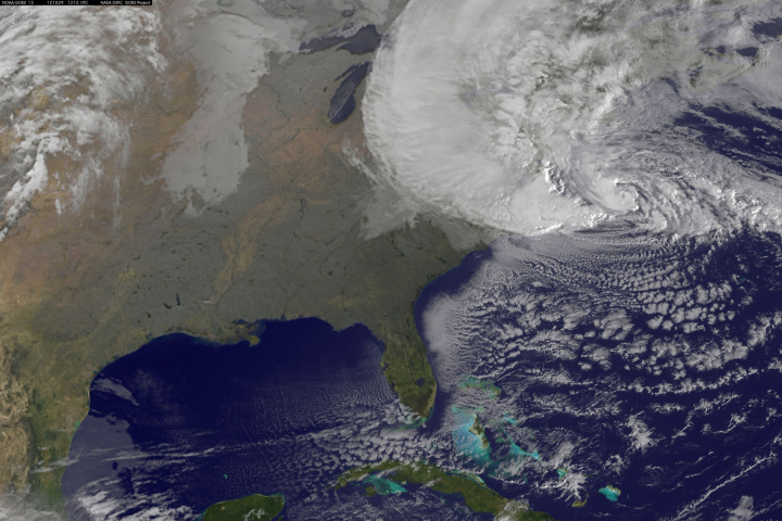
The October 2012 Frankenstorm Sandy brought rain, hail, snow, and high winds to Western Pennsylvania. We decided to ride the storm out in the workshop to work on a father and son project - to return a crystal radio to use.
We had built a crystal radio and revived an antique headset a few years ago as a school science fair project. We built the crystal radio on a breadboard and included an air variable capacitor, a 1N34A germanium diode, and fahnestock clips.
The Fahnestock clip was invented in 1907 is a classic simple wire connector that is both perfectly functional and looks great in a crystal radio breadboard project.
The 1N34A germanium diode starts to conduct around 0.1 volts. This makes it a very good choice for use as a detector in crystal radios.
The breadboard was repurposed from an old sports award. We used a belt sander to remove the finish and engraving. The process yielded a breadboard with an attractive two-tone appearance. This is a great way to save money too.
The air variable capacitor has an adjustable capacitance from 0 to 365 Pf. These are not easy to find. This type of air variable capacitor is worth searching for since they work very well and dress up the appearance of the breadboard. They can also be salvaged from vintage junk radios. The more common miniature tuning capacitors will work fine, though they don't looks as nice in an open breadboard project.
With the passage of time, our home-brew crystal radio had fallen into disrepair after being packed, stacked, and moved around. A crystal radio on a bread board is somewhat delicate and so it was no surprise that it was in need of a little TLC.
A crystal radio is a relatively simple device which makes it easy to troubleshoot. To repair it, KC2VSR reconnected a few broken connections with a soldering iron. We attached the radio to an antenna and ground and we were able to tune in a couple of strong local stations.
In part 2, we experiment with the radio.
Good DX and 73, NJ2X
© Michael W. Maher and NJ2X.COM, 2012. Unauthorized use and/or duplication of this material without express and written permission from this blog’s author and/or owner is strictly prohibited. Excerpts and links may be used, provided that full and clear credit is given to Michael W. Maher and NJ2X.COM with appropriate and specific direction to the original content.
| Frankenstorm Sandy October 29 |
We had built a crystal radio and revived an antique headset a few years ago as a school science fair project. We built the crystal radio on a breadboard and included an air variable capacitor, a 1N34A germanium diode, and fahnestock clips.
| Fahnestock Clip |
The Fahnestock clip was invented in 1907 is a classic simple wire connector that is both perfectly functional and looks great in a crystal radio breadboard project.
The 1N34A germanium diode starts to conduct around 0.1 volts. This makes it a very good choice for use as a detector in crystal radios.
| Diode Schematic Symbol |
The breadboard was repurposed from an old sports award. We used a belt sander to remove the finish and engraving. The process yielded a breadboard with an attractive two-tone appearance. This is a great way to save money too.
The air variable capacitor has an adjustable capacitance from 0 to 365 Pf. These are not easy to find. This type of air variable capacitor is worth searching for since they work very well and dress up the appearance of the breadboard. They can also be salvaged from vintage junk radios. The more common miniature tuning capacitors will work fine, though they don't looks as nice in an open breadboard project.
| Variable Capacitor Schematic Symbol |
A crystal radio is a relatively simple device which makes it easy to troubleshoot. To repair it, KC2VSR reconnected a few broken connections with a soldering iron. We attached the radio to an antenna and ground and we were able to tune in a couple of strong local stations.
![]() |
| Crystal Radio and Vintage Headphones |
![]() |
| Crystal Radio |
In part 2, we experiment with the radio.
Good DX and 73, NJ2X
© Michael W. Maher and NJ2X.COM, 2012. Unauthorized use and/or duplication of this material without express and written permission from this blog’s author and/or owner is strictly prohibited. Excerpts and links may be used, provided that full and clear credit is given to Michael W. Maher and NJ2X.COM with appropriate and specific direction to the original content.
October 28, 2012
Considerations For A New Antenna - Part 2: Installing a 6m Antenna
In "Considerations For A New Antenna - Part 1" we discussed the criteria and considerations for setting up new antennas in our new location. In this article, we share how we went about setting up our first antenna in the new location.
We decided our first effort would be to set up a 6m ground plane antenna on a mast mounted on top our chimney. 6m is a wonderful band offering DX possibilities along with access to local repeaters.
For this project we would need:
We ordered a Ronard chimney mast mounting kit and Winegard 5 foot mast and they arrived quickly. The Winegard mast was more substantial than expected. The mast was 18 gauge steel tubing without any visible seem. The Ronard chimney mast mounting kit included stainless steel straps and heavy duty hardware. The chimney mast mounting kit included very basic instructions for setting up the straps.
We had picked up an older 6m ground plane antenna brand new in the box at a ham fest several years ago for $20.00. We had used this antenna with a 18 foot painters pole for an easy-to-setup ARRL Field Day antenna. We used our MFJ-269 antenna analyzer to cut the antenna centered around the SSB DX calling frequency of 50.125 Mhz (see 6m band plan below).
We also had a lightning suppressor, electrical tape, self-sealing silicone tape, coaxial cable, UHF connectors, and the tools already available in our shack.
We next surveyed the work areas looking for hazards. It is critical before starting to make sure that any new antenna installation cannot come in contact with overhead wires or buried utilities. We confirmed that no hazards were present.
We assembled all the parts and tools at the base of the chimney and enlisted a helper. This job could be done by one man; however, two hams are better than one. It is considerably safer to work with a helper since ladders and heights are involved.
We also brought out a pair of 2m HT's to aid with communication between the roof-top work and the ground-work. This is so much effective than yelling back-and-forth at the top of your lungs and being misunderstood. We are hams after all. There is typically a fair amount of wind noise up on a roof that can interfere with being heard without the aid of a radio. This helped avoid a comedy exchange, "I said, send up a WRENCH not go sit on the BENCH!!!" or "What was that? Did you say, GO! or NO!?"
We attached an ICE suppressor bracket with 2 ICE lightning suppressors mounted to the top of the ground round. One lightning suppressor for use on 6m and the other for an HF antenna.
We placed the lightning suppressor and cabling within an enclosure to provide some protection from the elements.
Since our first QSO, we have enjoined joining into the Pittsburgh 6m repeater net and finding a few other local 6m repeaters we can reach. We are also eagerly awaiting a 6m opening when we can give 6m DX a workout with the new antenna and make progress toward our ARRL 6m DXCC award.
The 6m band is the "magic band" and has something to offer everyone - from DX'ing, repeaters, ragchew, CW, digital, ...
ARRL 6 Meter Band Plan, 50.0-54.0 MHz 50.000-50.100 CW and beacons
50.060-50.080 Automatically controlled beacons
50.100-50.600 SSB 50.125 SSB DX calling frequency 50.200 SSB domestic calling frequency (Note: Suggest QSY up for local & down for long-distance QSOs)
50.600-51.000 Experimental and special modes 50.700 RTTY calling frequency
50.800-50.980 Radio Control (R/C) channels, 10 channels spaced 20 kHz apart (new)
51.000-51.100 Pacific DX window
51.000-52.000 Newly authorized FM repeater allocation
51.100-52.000 FM simplex
52.000-52.050 Pacific DX window
52.000-53.000 FM repeater and simplex
53.000-54.000 Present radio control (R/C) channels, 10 channels spaced 100 kHz apart
73,
NJ2X
The NJ2X Kindle Edition is now available.
© Michael W. Maher and NJ2X.COM, 2012. Unauthorized use and/or duplication of this material without express and written permission from this blog’s author and/or owner is strictly prohibited. Excerpts and links may be used, provided that full and clear credit is given to Michael W. Maher and NJ2X.COM with appropriate and specific direction to the original content.
We decided our first effort would be to set up a 6m ground plane antenna on a mast mounted on top our chimney. 6m is a wonderful band offering DX possibilities along with access to local repeaters.
For this project we would need:
- 6m ground plane antenna
- Chimney mast mounting kit
- Standard 1.5 inch x 5 foot antenna mast
- Low-loss 50-ohm coaxial cable (we use Bury-FLEX 1.1 dB of attenuation /100 FT at 50 Mhz)
- UHF connectors
- 8-foot copper clad steel ground rod
- Lightning arrestor (we use ICE coaxial lightning/EMP suppressors)
- Solder
- Soldering iron
- Electrical tape
- Self-sealing silicone rubber tape
- Ladder
- Rope and bucket
- Crescent wrench
- Leather work gloves
- Pair of HT's (optional)
Parts
In days gone past, items such as chimney mast mount and masts were commonly available in local hardware or electronics stores serving the needs of customers with TV antennas. We went shopping in local area stores and found none had chimney mast mounts or even 5 foot antenna masts; though, they did have an 8-foot ground rod. The ubiquity of cable TV seems to have reduced the need for TV antennas. Thankfully, these items are still available through Internet retailers.We ordered a Ronard chimney mast mounting kit and Winegard 5 foot mast and they arrived quickly. The Winegard mast was more substantial than expected. The mast was 18 gauge steel tubing without any visible seem. The Ronard chimney mast mounting kit included stainless steel straps and heavy duty hardware. The chimney mast mounting kit included very basic instructions for setting up the straps.
We had picked up an older 6m ground plane antenna brand new in the box at a ham fest several years ago for $20.00. We had used this antenna with a 18 foot painters pole for an easy-to-setup ARRL Field Day antenna. We used our MFJ-269 antenna analyzer to cut the antenna centered around the SSB DX calling frequency of 50.125 Mhz (see 6m band plan below).
We also had a lightning suppressor, electrical tape, self-sealing silicone tape, coaxial cable, UHF connectors, and the tools already available in our shack.
Safety First
Amateur radio is generally a very safe activity. There are potential risks to consider and take the necessary precautions. Among these is coming in contact with high voltages and currents, falling from heights, and having something fall on you. Our motto is, "safety first" and this mindset helps us avoid accidents.Installation Preparation
The first step was call the local utilities and request them to identify buried cables and gas lines. They came out within a few days and marked everything clearly with spray paint and flags.We next surveyed the work areas looking for hazards. It is critical before starting to make sure that any new antenna installation cannot come in contact with overhead wires or buried utilities. We confirmed that no hazards were present.
We assembled all the parts and tools at the base of the chimney and enlisted a helper. This job could be done by one man; however, two hams are better than one. It is considerably safer to work with a helper since ladders and heights are involved.
We also brought out a pair of 2m HT's to aid with communication between the roof-top work and the ground-work. This is so much effective than yelling back-and-forth at the top of your lungs and being misunderstood. We are hams after all. There is typically a fair amount of wind noise up on a roof that can interfere with being heard without the aid of a radio. This helped avoid a comedy exchange, "I said, send up a WRENCH not go sit on the BENCH!!!" or "What was that? Did you say, GO! or NO!?"
Installing the Chimney Mast Mount
The Ronard chimney mast mount included directions for fastening the stainless steel strap to the strapping clip. However, no other directions were provided. The mount itself is a fairly simple device and perhaps assembly is self evident. Installation is another matter. Installing the mount took a bit of trial-and-error to get it right. Here are a few things we learned:- Wear leather gloves when handling the stainless steel strap. The strapping is razor sharp. We didn't think to bring gloves to the roof top and by the time the installation was complete our hands had a dozen or so nicks.
- Pre-bend the strapping into shape before placing around the chimney. The strapping wants to return to its coiled shape unless you counter this with new bends. It is much easier to handle the strap when it is in the approximate shape of the chimney than if it is in the approximate shape of a tightly wound coil.
- Wire cutters won't cut stainless steel strap. Perhaps there is a better tool? We didn't discover this until we were on the roof so we ended up using metal fatigue to break the strapping in the desired place.
- Prepare the strap and strapping clips on the ground. If we had it to do over again we would pre-cut the strap to the desired length and pre-install the strapping clips all on the ground. This would avoid the possibility of losing one of the small clips on or over the side of the roof. It would also be easier and provide more convenient access to tools in the workshop.
- We kept our hands free while climbing the ladder and roof and used a rope and bucket to hoist up parts and tools from the ground. Here is our helper made the biggest contribution.
Installing the 6m Ground Plane Antenna
Attaching the mast and ground plane antenna was the easiest part of the installation.- Build the antenna on the ground. The antenna has 5 main parts that needed to be assembled. Once assembled the antenna is light and somewhat bulky. We choose to build the antenna on the ground for ease and safety.
- Hoist up tools to the roof with the aid of a bucket and a line. Communicate with the helper on the ground with an HT. Make sure the helper stands well away from the roof line or where anything could fall.
- Hoist the mast from the ground to the roof with a line. We passed the line through the mast from one end to the other. We tied a wooden dowel to the rope at the end of the mast and hoisted it up. This kept the mast in the same orientation as the line and made it very easy.
- Hoist the antenna from the ground to the roof with a line. We tied the rope to the bottom of the antenna and also at the top. This allowed for an easy hoist in a vertical orientation to the roof.
- Hoist the coaxial cable from the ground to the roof with a line. We tied the rope to the coaxial cable and hoisted it up with ease. Take care there are no twists in the coax that could turn into a kink (bad for coax) while hoisting.
- Seal the coaxial connection. Some people prefer coax seal. We prefer applying a couple of tight layers of good quality electrical tape followed by a wrapping with self-sealing silicone tape. This will prevent water intrusion and corrosion.
- Secure the coax to the mast with electrical tape or cable ties. This prevents the coaxial cable from bouncing around against the mast in high winds. Provides some strain relief as well.
![]() |
| 6m Ground Plane Vertical Antenna Close Up |
Installing RF Grounding System
We used a step ladder to stand on to drive the 8ft ground rod with a 8 pound hammer. This made it easy to keep the hammer on-target as it went into the ground. We switched to a larger sledge to drive the last foot or so.We attached an ICE suppressor bracket with 2 ICE lightning suppressors mounted to the top of the ground round. One lightning suppressor for use on 6m and the other for an HF antenna.
We placed the lightning suppressor and cabling within an enclosure to provide some protection from the elements.
![]() |
| Lightening arrestor system |
First 6m QSO
We connected the cabling to our Kenwood TS-480SAT and powered up. We had a local Pittsburgh 6m repeater already programmed into memory (51.740 Mhz with a PL tone of 100.00 Hz) so we dialed it up and found a group of hams in a ragchew. So far so good on receive. We were wondering if the antenna would tune up and transmit? We hit, "tune" and sure enough it tuned immediately. This was a good sign that everything was in order. We waited for a pause and then transmitted giving our call. One of the hams came back immediately acknowledging our call and inviting us into the group. Voila! 6m ground plane vertical antenna project success!| 6m Ground Plane Antenna mounted on chimney |
Since our first QSO, we have enjoined joining into the Pittsburgh 6m repeater net and finding a few other local 6m repeaters we can reach. We are also eagerly awaiting a 6m opening when we can give 6m DX a workout with the new antenna and make progress toward our ARRL 6m DXCC award.
The 6m band is the "magic band" and has something to offer everyone - from DX'ing, repeaters, ragchew, CW, digital, ...
ARRL 6 Meter Band Plan, 50.0-54.0 MHz 50.000-50.100 CW and beacons
50.060-50.080 Automatically controlled beacons
50.100-50.600 SSB 50.125 SSB DX calling frequency 50.200 SSB domestic calling frequency (Note: Suggest QSY up for local & down for long-distance QSOs)
50.600-51.000 Experimental and special modes 50.700 RTTY calling frequency
50.800-50.980 Radio Control (R/C) channels, 10 channels spaced 20 kHz apart (new)
51.000-51.100 Pacific DX window
51.000-52.000 Newly authorized FM repeater allocation
51.100-52.000 FM simplex
52.000-52.050 Pacific DX window
52.000-53.000 FM repeater and simplex
53.000-54.000 Present radio control (R/C) channels, 10 channels spaced 100 kHz apart
Shortwave Reception
An unexpected side benefit was the antenna's receive capabilities. While tuning around HF we discovered the antenna performed nicely as a shortwave receive antenna. We were surprised how well it received shortwave stations. We attribute the quiet performance to having a good RF ground and installing the antenna above the roof line. In the past, we have always used horizontal wire antennas (i.e. long wire, dipole, and fan-dipoles) for shortwave reception. This antenna has given us a new appreciation for a VHF vertical for shortwave reception. This is also something to keep in mind when in an emergency situation - a VHF antenna is an asset for both VHF and HF reception.73,
NJ2X
The NJ2X Kindle Edition is now available.
© Michael W. Maher and NJ2X.COM, 2012. Unauthorized use and/or duplication of this material without express and written permission from this blog’s author and/or owner is strictly prohibited. Excerpts and links may be used, provided that full and clear credit is given to Michael W. Maher and NJ2X.COM with appropriate and specific direction to the original content.
October 27, 2012
CQ World Wide DX Contest
10m opened up worldwide to the great enjoyment of hams participating in this weekend's CQ World Wide DX Contest. I joined in the fun and participated in the contest with my modest station. The QSO's were plentiful. I completed 170 QSO's with 97 countries earning a final score of 47,854.
The cold and wet weather provided additional motivation to stay in the shack. No sense in getting to know "Sandy" also nicknamed the Frankenstorm any more than on a first name basis.
We rather liked the Italian IO5O qrz.com webpage with the club's live streaming video of their participation in the contest. A unique way to view radio. Thanks for the contact Ten-Fifty Contest Group.
73,
NJ2X
The cold and wet weather provided additional motivation to stay in the shack. No sense in getting to know "Sandy" also nicknamed the Frankenstorm any more than on a first name basis.
We rather liked the Italian IO5O qrz.com webpage with the club's live streaming video of their participation in the contest. A unique way to view radio. Thanks for the contact Ten-Fifty Contest Group.
73,
NJ2X
October 26, 2012
Warm Glow of Linear Amplifier Tubes
October 24, 2012
Antenna Coaxial Cable Conduit Fill Considerations
Conduit fill is the percent of the area inside the conduit taken up by cables. Conduit fill is an important consideration when selecting and planning your antenna projects since it is not possible to use 100% of the conduit's area. There is no sense in going through the expense and effort of trenching, laying conduit, and pulling your antenna coaxial cable only to find later that the conduit is too small to support the area consumed by the cables.
We recently ran across two handy Internet resources related to conduit fill: Conduit Fill Chart and Conduit Fill Calculator.
Here is an example of the conduit fill calculators output:
**Warning: There is some probability of
jamming.
73,
NJ2X
We recently ran across two handy Internet resources related to conduit fill: Conduit Fill Chart and Conduit Fill Calculator.
Here is an example of the conduit fill calculators output:
| The conduit fill is: 17.9% |
| Based On: | |
| Conduit Type: | Rigid PVC Conduit, Schedule 40 |
| * Conduit Size: | 2 inch(es) |
| Internal Diameter: | 2.047 (in.) |
| Conductor #1: | 3 conductors with an outside diameter of .5 inches. |
| Conductor #2: | 0 conductors with an outside diameter of 0 inches. |
73,
NJ2X
Subscribe to:
Posts (Atom)